20+ sysml component diagram
Each component is responsible for one clear aim within the entire system and. Block Definition Diagram bdd.

Automatically Convert Java Code Into Uml Coding Java Converter
As such there is no correct diagram.

. Sysml classic by edouard pitocco. This means that your SysML diagrams are more flexible and expressive than UML. SysML uses seven of UML 2s 14 diagrams and adds two additional diagram types.
Beranda 20 activity Images sysml. The SysML diagram is composed of 9 diagram types and allocation tables for mapping language elements across diagram types. The SysML is composed of nine 9 diagram types and Allocation Tables for mapping language elements across diagram types.
A Component diagram has a. Use Createlys easy online diagram editor to edit this diagram collaborate with others and export results to multiple image formats. A SysML Package diagram provides a means of visualizing the organization of a complex model into recognizable containers which helps you to group the structures of the model and define.
Systems modelling language SysML is an extension of UML that has been modified for systems engineering. Create SysML diagrams faster than ever with our online SysML templates. 20 sysml activity diagram Kamis 15 September 2022 Edit.
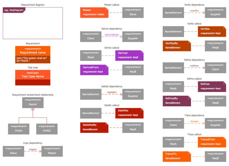
Modelers need to produce. A Block Definition Diagram is a static structural diagram that shows system components their contents Properties Behaviors Constraints. Requirement diagram req Structure Diagrams.
Show all templates for. A component diagram breaks down the actual system under development into various high levels of functionality. While both can document software information and.
Diagram A Diagram B Diagram C The two diagrams A and B represent two possible methods for determining flight range. The internal block diagram or ibd resembles a traditional system block diagram and shows the connections between parts of a block. Requirement Diagram 4 See All.
The frame of the internal block diagram always. A Component diagram illustrates the pieces of software embedded controllers and such that make up a system and their organization and dependencies. The steps in an activity diagram are actions.

Beyond Spreadsheets Engineering Com Systems Engineering Software Development Life Cycle Systems Thinking

Example Of A Sysml Requirements Diagram Download Scientific Diagram Diagram Example System

Use Case Diagram Of Whatsapp Use Case Computer Generation Relationship Diagram

Sysml Solution Systems Engineering Software Development Solutions

Sysml Solution Software Development Solutions Diagram Chart

Datastore Node Example Activity Diagram Activities Sample Resume

Introduction To Systems Modeling Language Sysml Part 1 Language Systems Engineering System

Sysml Solution Flow Chart Diagram Design State Diagram

Sysml Solution Diagram Design Activity Diagram Diagram

Sysml Solution Solutions Systems Engineering Software Development

Eclipse Sirius Example System Architecture Process Chart Sirius

Sysml Solution Software Development Diagram Chart Solutions

Sysml Solution How To Apply Software Development Systems Engineering

Omg Sysml Systems Engineering System Model System

Datastore Node Example Activity Diagram Activities Sample Resume

Sysml Package Diagram Deployment Model Structure Software Development Systems Engineering Diagram Chart

Design Scenarios Communicating The Small Steps In The User Experience Use Case Diagram Design User Story Mapping